Guides / Process
Motor Lamination Stamping: Choosing Electrical Steel, Die Type and Stacking Method
October 29, 2026
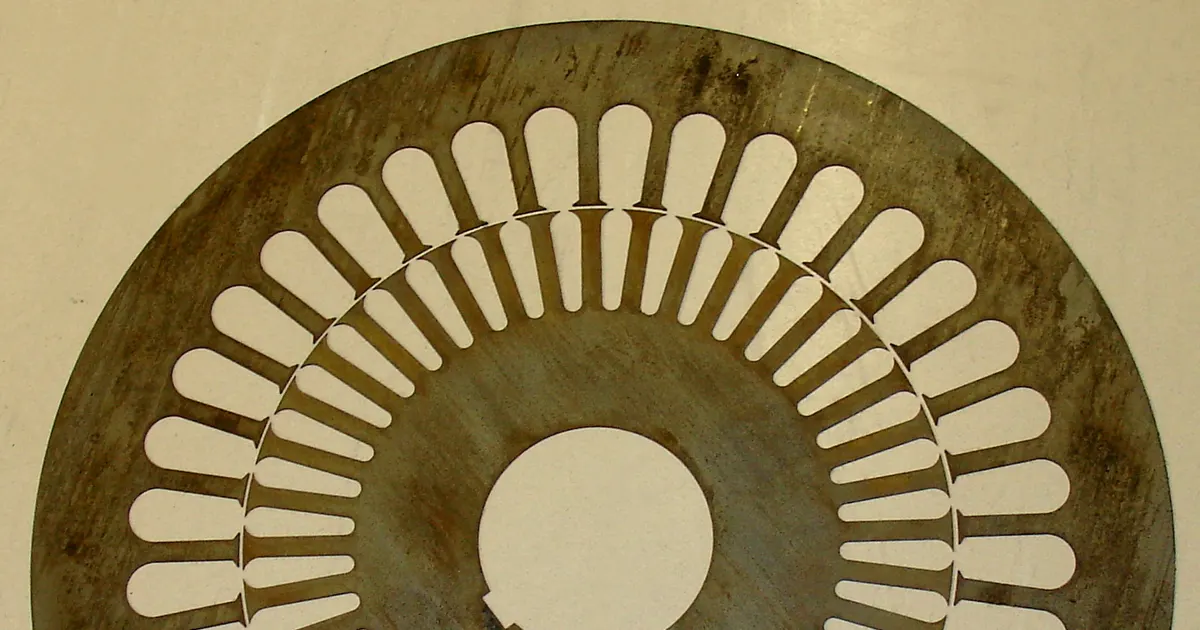
Every electric motor and generator has a core of electrical steel, shaped into a stator and often a rotor. The core carries magnetic flux, and to keep losses low it is built from many thin sheets stacked together, not cut from a solid block. Each sheet is a lamination: a flat disc or ring with slots for the windings, stamped from a coil of thin silicon steel at high speed.
Lamination stamping looks simple in a drawing and is demanding in practice. Thin hard material, tight tolerances, burr limits that protect insulation and stacks with dozens or hundreds of sheets all raise the bar. This guide covers the steel, the dies, the stacking methods and what to put on an RFQ.
Electrical steel
Electrical steel is iron with a few percent silicon. The silicon raises electrical resistance, which cuts eddy current loss, and improves magnetic behavior. Two families exist. Non-oriented steel has similar magnetic properties in all directions and is used in motors and generators, where flux changes direction. Grain-oriented steel has strong properties along the rolling direction and is used in transformers.
Grades are named by thickness and core loss. In the European system, a grade such as M270-35A is 0.35 mm thick with a maximum core loss of 2.7 watts per kilogram under standard test conditions. In the US system, designations like M19 appear. Lower loss grades carry more silicon and cost more.
Two supply conditions matter:
- Fully processed. The steel has its final magnetic properties at delivery. After stamping, no anneal is needed, though some shops add a stress relief.
- Semi-processed. The steel needs a final anneal after stamping to develop its properties and relieve stamping stress. The anneal adds a process step and distortion risk but can give lower loss.
Each sheet carries an insulating coating, classified by ASTM A976. The coating type affects insulation, punchability, weldability and heat resistance, and it can be damaged by tools and by welding.
Thickness and use
| Thickness | Typical use | Notes |
|---|---|---|
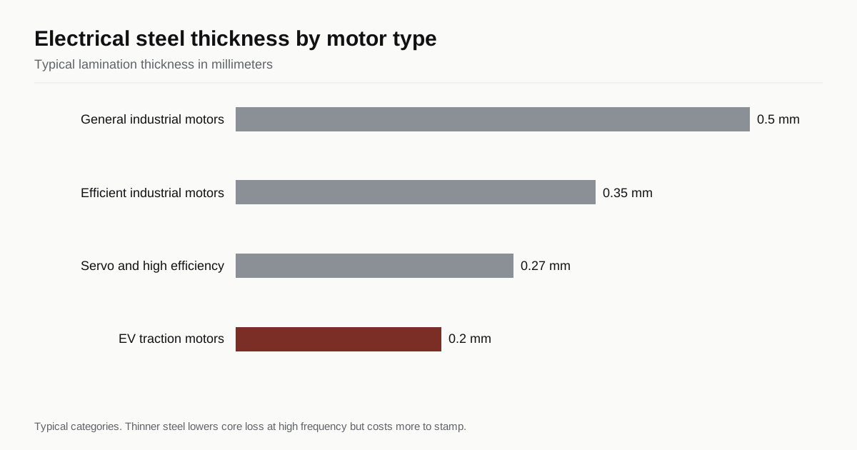
| 0.50 mm | General industrial motors, appliances | Lower cost, higher loss at high frequency |
| 0.35 mm | Efficient industrial motors, generators | Common compromise |
| 0.27 to 0.30 mm | High efficiency and servo motors | Lower loss, harder to stamp |
| 0.20 mm and below | High speed and EV traction motors | Lowest loss, fragile, highest cost |
These are typical categories. Thinner steel lowers loss at high frequency, but it is harder to feed and stack, and it needs more sheets per stack.
Die types
Several die approaches make laminations, and the choice depends on volume, accuracy and design.
- Compound dies cut the outer and inner diameter in one stroke. They give good concentricity and flatness but need a separate step for slots.
- Notching dies cut slots one at a time, indexing the blank around between hits. Cheap for prototypes and low volume, slower per part.
- Progressive dies blank the rotor and stator, pierce slots and cut off the finished lamination in one tool. High speed and high volume.
- Interlocking progressive dies add small stamped tabs that snap each sheet to the one below, so the stack builds inside the die.
A common material-saving layout cuts the rotor out of the stator’s center, since the stator’s inner hole is the rotor’s outer shape. Rotors and stators then come from the same coil with little scrap. Progressive dies for laminations are precise and expensive, and the tooling often runs into six figures in US dollars for complex designs, a typical order of magnitude rather than a quote. See progressive die vs transfer die vs deep draw for the general comparison.
Tooling material
Silicon steel is abrasive and hard on tools. Cutting parts in lamination dies are usually tungsten carbide, which lasts many times longer than tool steel and keeps burr low. Carbide costs more and chips if it is mishandled, so tooling is precise and handled carefully. Sharpening intervals are long compared with other work but each grind must be accurate. See stamping die maintenance and tool life for the records and questions that apply.
Burr and magnetic properties
Burr is the most important quality parameter on laminations. The reasons:
- A burr bridges the insulating coating between sheets, so eddy currents flow across the stack and core loss rises.
- A burr increases stack height, so the stack does not reach its design length at the specified pressure.
- A tall burr can scratch winding insulation in the slots.
Typical burr limits are a few hundredths of a millimeter for thin steel, tighter for thinner sheets, and the burr direction is set so all sheets stack the same way. Measurement is by microscope or profile instrument. See stamping burr height.
Cutting also changes the steel near the edge. The shearing and the burr alter the magnetic properties within a small distance of the cut, which raises local loss. This cut-edge effect is bigger on small teeth and thin steel. A stress-relief anneal after stamping recovers some of it. Shops can advise on sharpness and clearance to keep the damaged zone small.
Stacking methods
Once the laminations are cut, they must be held together. Common methods are:
- Interlocking tabs. Formed in the die, tabs lock each lamination to the next. Fast and low in cost, but the tabs add some local loss and limit stack flexibility.
- Laser welding. Welds along the outside diameter fix the stack. Common for larger stacks, but welding can short laminations and damage the coating along the weld line.
- Bonding varnish. A bonding coating on the steel is cured under heat and pressure to glue the stack, which avoids welds and tabs and suits low loss designs.
- Cleats, rivets or bolts. Mechanical fasteners for large or special stacks.
Each method affects loss, stack strength, tolerance and cost. State the method on the print and ask the shop what it has run.
Tolerances
Laminations carry tight dimensional requirements. Typical callouts include:
- Inner and outer diameter and their concentricity
- Slot width, depth and position
- Stack height and squareness
- Slot alignment through the stack
- Flatness of the individual sheet
Thin material complicates all of these. Concentricity depends on the die and the press, and stack alignment depends on the stacking method. Ask the shop what it holds on similar parts, and mark the critical dimensions only. See metal stamping tolerances.
Prototype and low volume routes
Before committing to a progressive die, designers often build prototypes by laser cutting or wire EDM. These methods need no tooling, but they change the steel near the cut edge, with heat from a laser and different edge effects from EDM, and the magnetic properties of a prototype may not match the stamped part. If loss numbers matter, test with a stamped sample, or ask the shop to run a short-run notching die. The metal stamping vs CNC machining vs laser cutting guide explains where each process fits.
Press speed, feeding and strip handling
Lamination dies run on high-speed presses, with stroke rates in the hundreds per minute for small laminations and lower for large ones. Thin steel is fed through precise rollers, and the strip must be flat, with low camber and a clean edge. A slight bow in the coil shows up as a lamination that does not sit flat. Material is also lightly oiled to protect it in transit, and the oil is controlled so that it does not interfere with the insulation or with bonding varnish. Ask the shop how it handles strip tension, camber and oil, and whether it uses a straightener. See coil thickness and width tolerance for the strip properties that matter.
Because the steel is brittle at the edge and the dies are carbide, a double blank or a slug jam can chip the tool. Sensors that stop the press on a misfeed matter even more here than on a bracket die. See in-die tapping and die sensors for the types of protection used.
Material yield and cost drivers
Electrical steel is expensive, so material yield decides much of the cost. A progressive layout that cuts the rotor from the stator center recovers material that would otherwise be scrap. Segmented stators, where the core is made from individual tooth segments or arcs, can nest more tightly than full rings and cut waste further, though they add assembly steps. The coil width should match the lamination diameter plus a margin, and a standard coil width may force extra waste.
Other cost drivers are:
- Tooling. Carbide, tight tolerances and the interlock features make lamination dies costly, and they are paid back over volume.
- Steel grade and thickness. Lower loss and thinner steel cost more per kilogram.
- Stacking and bonding. Bonding varnish and welding add steps.
- Annealing. A post-stamping anneal adds a furnace pass and handling.
- Inspection. Burr, stack height and slot alignment checks add time.
Ask each shop for its material yield and the coil width it assumes. A small change in lamination diameter or slot design can move the coil width and the price. For quote line items, see how to read a metal stamping quote.
Notes for EV and high speed motors
Traction motors for vehicles push the limits. The steel is often 0.20 to 0.30 mm thick, with low core loss, and the rotor spins at high speed, so strength and balance matter. Rotor laminations may need bonding or specific stacking to survive the stress. Volumes ramp fast, and programs ask for strict capability data and traceability back to the coil. A shop that can run thin steel at volume, with carbide tooling and proven burr control, is a short list. State the speed, the thickness and the program ramp in the RFQ so the shop can check press capacity and tool design. The documents buyers often request appear in the PPAP primer.
What to put on the RFQ
- Steel grade, thickness and supply condition, fully or semi-processed
- Coating class
- Lamination drawing with slot geometry and critical dimensions
- Burr limit and direction
- Stack height, count and stacking method
- Anneal or stress relief requirement
- Annual volume and release schedule
- Tooling ownership, storage and spare parts
The metal stamping RFQ checklist lists the other fields.
Checklist before you send
- Choose the steel by loss, thickness and cost.
- Decide fully or semi-processed material.
- Set burr limit and direction.
- Pick the stacking method.
- Decide how prototypes will be made.
- Agree on tooling ownership and maintenance.
When the print is ready, send the RFQ and compare shop replies within 24 business hours.
Frequently asked questions
Why are motor cores made of thin laminations?
A solid iron core would carry large eddy currents that waste energy as heat. Stacking thin insulated sheets breaks up those currents, so losses are much lower. Thinner sheets cut losses further, which is why high speed and EV motors use very thin steel.
Why does burr matter on a lamination?
A burr can bridge the insulation between neighboring sheets and let eddy currents flow across them, which raises core loss. Burr also stops the stack from compressing to the intended height.
What is an interlocking lamination?
A lamination with small stamped tabs and matching recesses, so that sheets snap together as they are stacked in the die. It avoids welding or gluing for many designs.
Need a quote for this part?
Send the print. We match you with up to 3 stamping shops and reply within 24 business hours.
Send my RFQ