Guides / Process
EMI Shield Stamping: Material, Flatness and Packaging for Board Level Shields and Enclosures
October 25, 2026
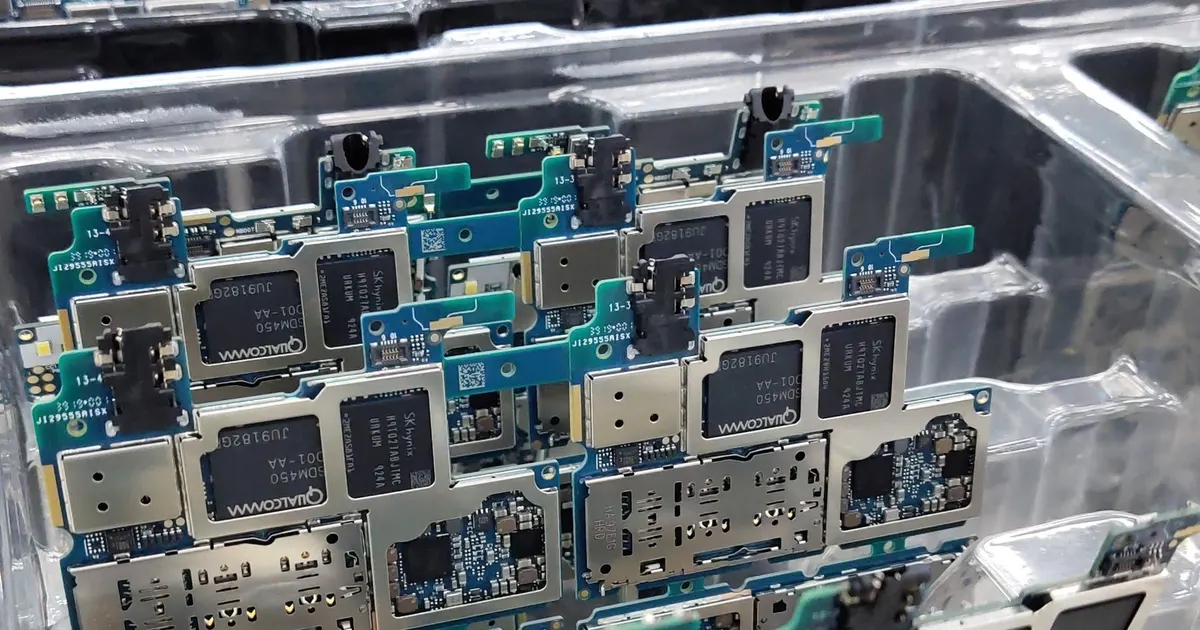
Electronics leak. A processor, a radio and a power converter all emit electromagnetic energy, and each is sensitive to what the others emit. A thin metal shield, soldered over a section of the board, contains the noise and blocks stray signals. These shields are among the smallest and most precise stamped parts in common use, and they are made by the billion.
This guide covers the two main families, board level shields and enclosures, the materials that suit them and the details that decide whether a shield works on the assembly line.
Board level shields
A board level shield, often called a shield can, is a small metal box open on one side that sits over components on a printed circuit board. Its feet are soldered to ground pads on the board, which closes the circuit with the board’s ground plane.
There are two common designs:
- One-piece shields. A single drawn or folded can with solder feet. Low in cost and height, but components under it cannot be reached without removing the can.
- Two-piece shields. A frame soldered to the board and a snap-on lid. The lid comes off for inspection or rework, which helps in test and repair.
Both are stamped from thin strip, typically a tenth to a third of a millimeter thick, and formed into a box. Corners are either drawn, folded and welded or formed with tabs. Shields are small, from a few millimeters to a few tens of millimeters across, and the tolerances are tight.
Enclosures and larger shields
Larger shielded boxes, cabinet covers and RF enclosures are made from heavier sheet, often tin-plated or zinc-coated steel, aluminum or stainless, with seams, gaskets or spring fingers to close the gaps. At this scale the die, material and finish questions resemble those for appliance housings, covered in appliance stamping. The shielding effectiveness depends on the gaps and openings, more than on the metal.
Material choices
| Material | Strengths | Limits | Typical use |
|---|---|---|---|
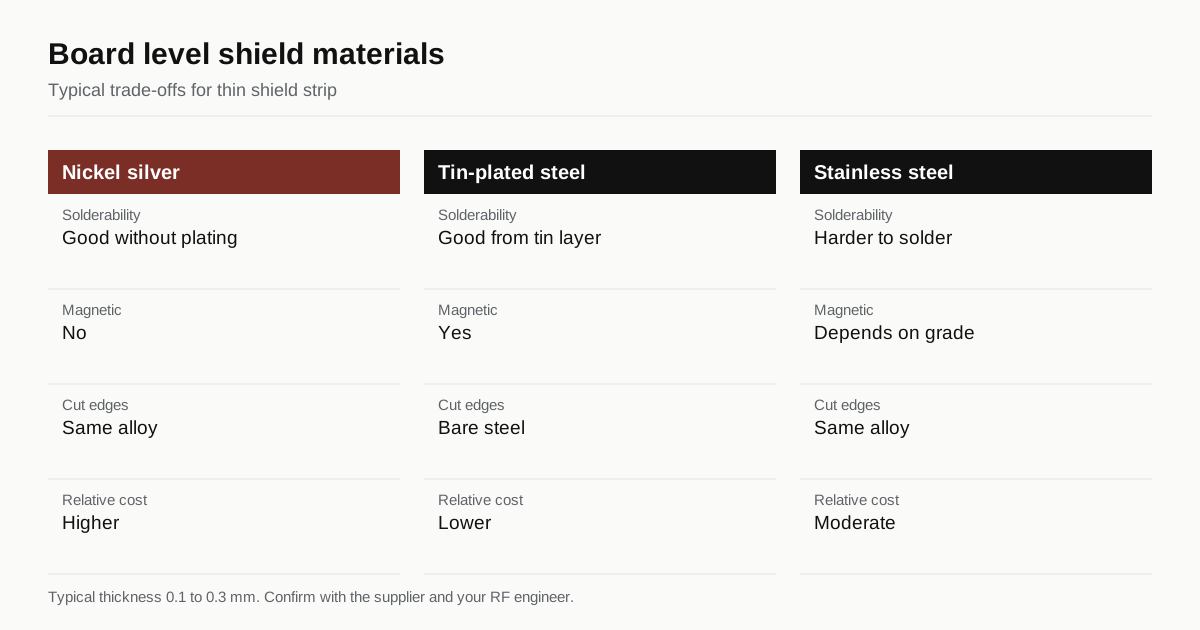
| Nickel silver, such as C75200 | Solders well, non-magnetic, corrosion resistant, good forming | Higher cost | Board level shields, visible parts |
| Tin-plated cold rolled steel | Low cost, magnetic shielding at low frequency, solderable plating | Cut edges are bare steel and can rust | Cost-driven board level shields |
| Stainless steel | Strong, tough, corrosion resistant | Harder to solder, work hardens | Ruggedized shields, thin frames |
| Brass or copper alloys | Good conductivity and forming | Soft, tarnish without plating | Special cases |
| Beryllium copper | High spring force | High cost, special handling | Spring fingers and gaskets |
The reasoning is practical. Nickel silver has a pleasing silver color, resists corrosion and solders readily without plating, which makes it a default for board level cans. Tin-plated steel is cheaper and offers some magnetic shielding because steel is ferromagnetic. See pre-plated strip vs plating after stamping for the edge issue with tin-plated strip. For fingers and gaskets, see beryllium copper stamping and copper, brass and phosphor bronze strip.
What decides shielding performance
A shield works by surrounding a circuit with conductive metal. Its effectiveness at a given frequency depends on three things:
- Material and thickness. At high frequencies, even a thin conductive layer reflects most energy. Magnetic materials add benefit at low frequencies.
- Openings. Holes, slots and seams leak. A common design rule is to keep the longest dimension of an opening well below the wavelength of the highest frequency of concern, often less than one twentieth.
- Contact to ground. A shield that is not well grounded works poorly. Solder joints, gasket pressure and finger contact all matter.
The stamper cannot design the shield, but it can hold the hole sizes, seam gaps and flatness that the design assumes. Mark critical openings and gaps on the print.
Flatness and coplanarity
A shield is soldered by reflow. The feet must touch the board pads evenly, or some joints open. The measure is coplanarity, the flatness of the solder feet as a group, and typical limits are a few hundredths of a millimeter to about a tenth. A shield that is bowed or twisted fails this check.
Thin strip springs back and bows after forming, so shops control it through die design, a flattening step and gentle handling. State the coplanarity limit, the measuring method and the datum features. Burrs on the feet change contact, so set a burr limit and direction. See stamping burr height.
Pick-and-place features
Assembly lines place shields with vacuum nozzles, the same as other chips. That requires:
- A flat, clean pickup area of at least the size the nozzle needs, often a few millimeters across
- A stable center of gravity, so the part does not tilt on the nozzle
- Dimensions inside tape pocket tolerance, so the part fits the carrier tape without sticking
- No sharp burrs or oil film that interfere with vacuum or contaminate the board
Venting also matters. During reflow, trapped air and flux vapor need an escape, so many shields carry small vent holes sized to keep shielding. Tell the shop how the shield will be placed and soldered, and ask it to propose pickup area and venting.
Packaging in tape and reel
Shields for automated assembly ship in embossed carrier tape on reels, packed to the electronics industry standard for tape dimensions. Parts are placed in tape pockets by a taping machine at the shop or by an outside packer. The packaging adds cost and a quality check, since a pocket with a skewed part stops the assembly line. Ask the shop whether it tapes in house, what it checks and how it handles reel labeling and traceability. For lower volumes or rework parts, trays can be used.
Process and tooling
Board level shields are made in high-speed progressive dies, where the strip is blanked, formed, sometimes drawn at the corners and cut off as a finished can. Tooling is precise and costs more than a bracket die, because tolerances on small features are tight, and tool material is often carbide. Thin strip needs tight guide fits and clean feeding. See progressive die vs transfer die vs deep draw for how the die types compare.
Thin strip also demands strip tolerance control. A few percent in thickness changes spring force on lid clips and coplanarity. See coil thickness and width tolerance.
An opening size example
The rule of keeping openings below one twentieth of a wavelength gives numbers you can check. Wavelength in air is the speed of light divided by frequency. At 2.4 GHz it is about 125 mm, so one twentieth is roughly 6 mm. At 5 GHz the wavelength is about 60 mm and one twentieth is about 3 mm. At 10 GHz it is about 30 mm and one twentieth is about 1.5 mm. A vent hole or a seam gap larger than that limit becomes a leak at the stated frequency.
The numbers explain why shields for higher frequency radios carry smaller vent holes and tighter lid fits. They also show why a gap at a corner, where two edges meet imperfectly, can matter more than a large panel. The stamper holds the gap tolerance, and the RF engineer sets the limit. If a seam or opening is critical, put the limit on the print, not only in a separate specification.
Inspection of small thin parts
Shield cans are too small and too numerous for manual inspection of every feature. Shops use:
- Vision systems that measure outline, hole positions and coplanarity from images, often in line with the tape and reel machine
- Optical sorting that rejects parts with burrs, dents or missing features
- Sample measurement by microscope or coordinate measuring machine at set intervals
- Solderability testing on a sample, where the finish demands it
- Cleanliness checks on a rinse sample, where contamination matters
Ask what the shop inspects on every part and what it samples. Because a defect stops an assembly line, many buyers require full inspection of the features that affect placement. First article and capability data are common requests. The PPAP primer lists the documents that electronics and automotive buyers often ask for.
Cleanliness and oil
Stamping uses oil, and oil on a shield interferes with solder and with vacuum pickup. Shops use stamping lubricants that evaporate or wash off cleanly, and they add a wash or bake step before packing. If your process is sensitive, say what residues are acceptable and how they are tested. Handling also matters. Fingerprints leave salts that affect solderability on bare metal, so parts are handled with gloves or machines, and packed in sealed bags or tape. State storage conditions and shelf life for plated parts, since tin oxide builds up over time and lowers solderability.
Cost drivers and design tips
Shield cost follows material, tooling and reel packaging. Nickel silver costs more than tin-plated steel, and the difference matters at millions of parts. Tooling is expensive because the tolerances are tight and the die runs at high speed. Several choices cut cost:
- Use standard sizes where the design allows. A shop with a tool family for common can sizes may adapt an existing die, which saves tooling cost and time.
- Keep the height low and the walls simple. Deep corners need more draw operations.
- Loosen tolerances on features that do not matter, such as the outline of a non-critical rim.
- Combine part numbers. One frame that fits several lids reduces tool count.
- Plan reel quantities. A minimum reel size and release schedule affect packing cost and inventory.
Ask the shop which sizes it already tools, and whether a small change to your outline would fit an existing die. For the line items that move quotes, see how to read a metal stamping quote.
What to put on the RFQ
- Material, alloy, temper and thickness
- Plating or finish, with the standard
- Outline, height and critical openings
- Coplanarity limit and method
- Burr limit and direction
- Pickup area, venting and lid fit requirements
- Reflow profile and solderability needs
- Packaging, tape size and reel quantity
- Cleanliness requirement
- Annual volume and release schedule
The metal stamping RFQ checklist lists the other fields.
Checklist before you send
- Decide one-piece or two-piece.
- Choose the material by solderability, cost and environment.
- Mark critical openings and seam gaps.
- Set coplanarity and burr limits.
- Describe how the shield will be picked and soldered.
- Define the packaging.
When the print is ready, send the RFQ and compare shop replies within 24 business hours.
Frequently asked questions
What is a board level shield?
A small metal can or frame and lid that is soldered over a part of a circuit board. It blocks electromagnetic interference from reaching sensitive circuits, and it keeps noisy circuits from disturbing others.
Why are shields sold in tape and reel?
Surface mount assembly machines pick parts from reels, so board level shields are packed in carrier tape to be placed automatically with other components. The part needs a flat pickup area and tight dimensions for that.
Which material is best for an EMI shield?
It depends on the frequency, the solder process and the cost target. Nickel silver is common for solderability and appearance, tin-plated steel is common for cost and magnetic shielding, and stainless suits tough environments. Ask the shop and your RF engineer.
Need a quote for this part?
Send the print. We match you with up to 3 stamping shops and reply within 24 business hours.
Send my RFQ